Part Programs
Manufacturing decisions seen through the part.
These representative programs show how geometry, tolerance, finish and order stage shape a practical CNC machining and inspection route.
The examples describe common sourcing requirements. They are not published customer claims or unverified performance results.
Typical Programs
Different industries. Different control priorities.
Each route begins with the released files and the requirements that determine function, assembly and appearance.
 PROGRAM / 01
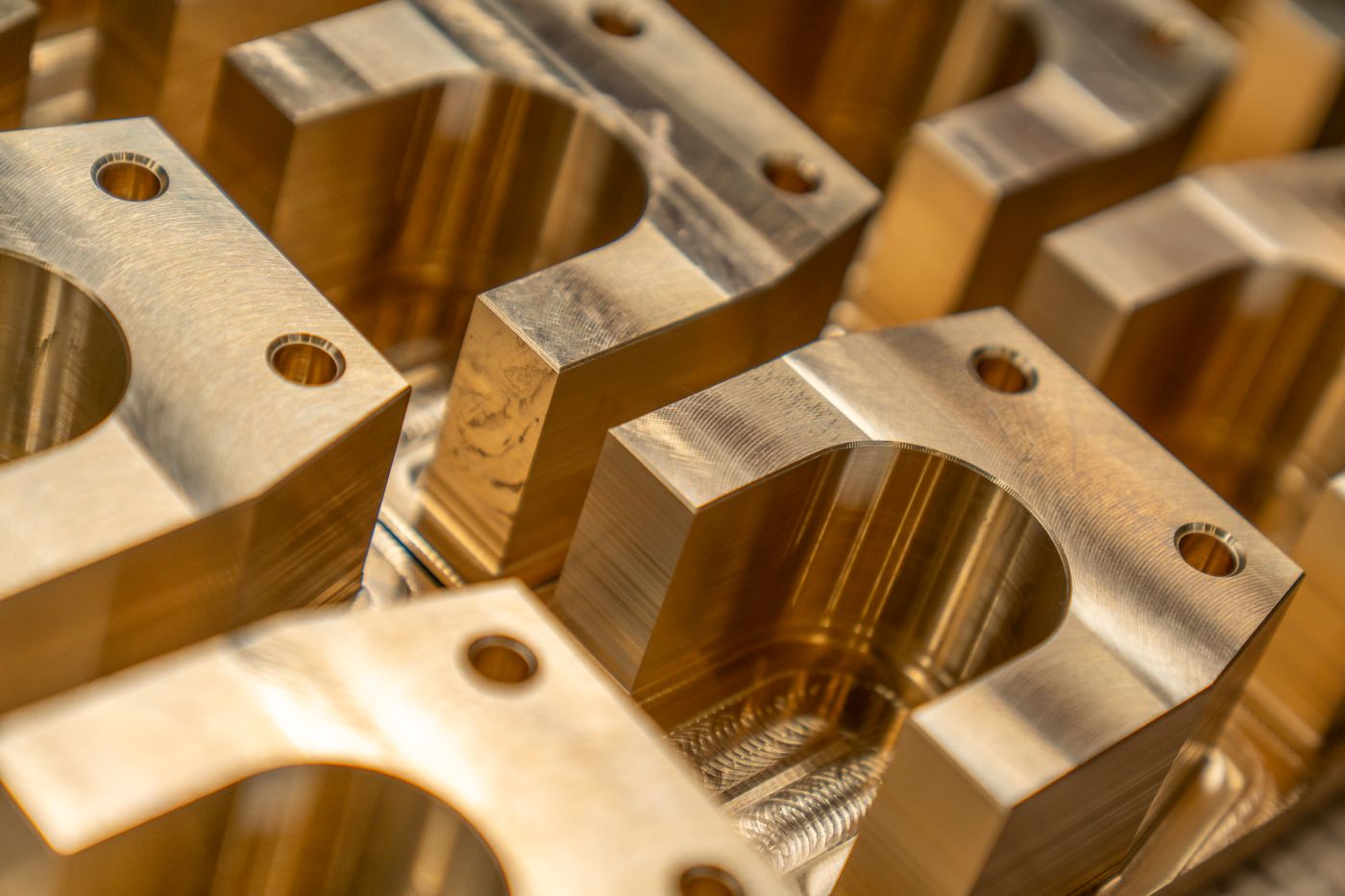
Multi-side actuator bracket
A complex aluminum bracket with threaded interfaces and datum relationships that control downstream assembly alignment.
Access and feature relationships
Multi-side milling
Datums and threaded interfaces
 PROGRAM / 02
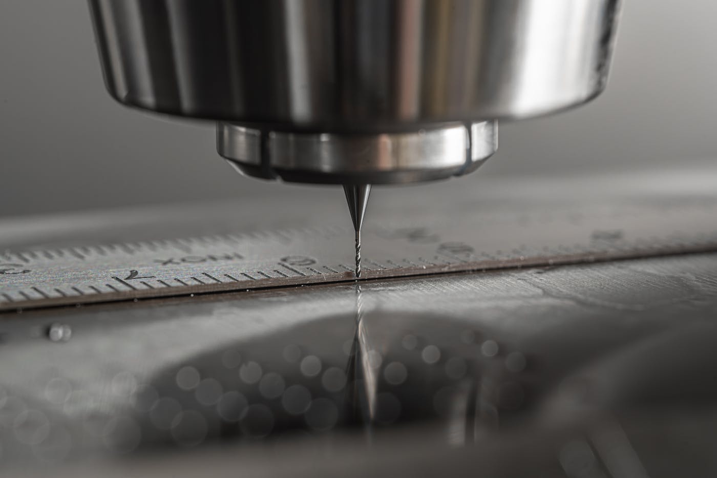
Prototype housing to repeat batch
An evolving enclosure program that must support design validation first and a stable low-volume route after approval.
Revision changes and cosmetic zones
Prototype then repeat plan
Revision and finish consistency
 PROGRAM / 03
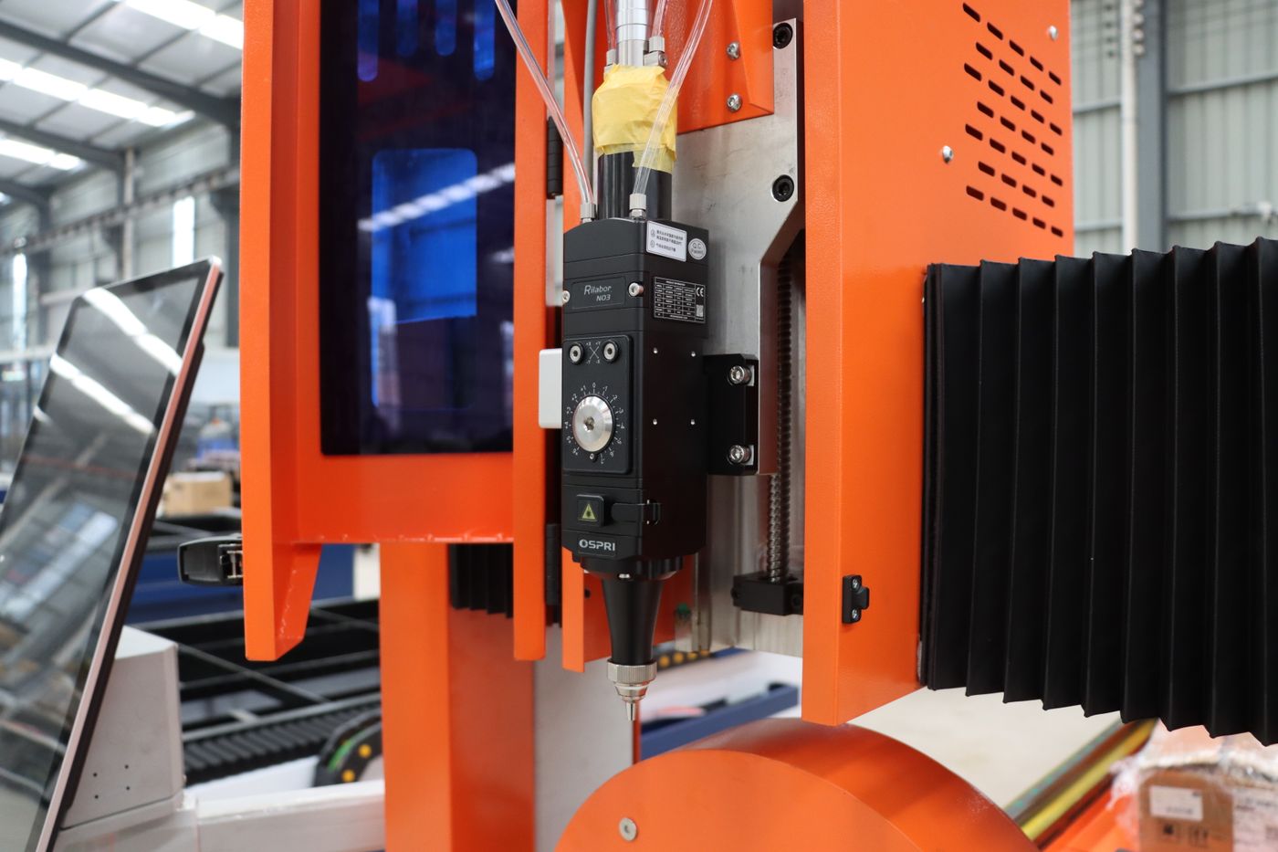
Precision mount with finished surfaces
A compact mount combining controlled bores, fine features and visible surfaces prepared for final equipment assembly.
Functional and cosmetic surfaces
Precision milling and finish
Bores, faces and appearance
 PROGRAM / 04
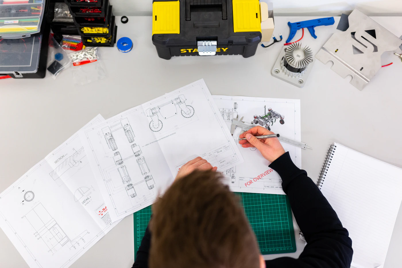
Replacement part for an active machine
A practical replacement component where fit, material and delivery continuity matter more than unnecessary cosmetic requirements.
Existing interfaces and downtime
Fit-led machining plan
Mating features and repeat supply
From Requirement to Route
A useful case record explains the decisions.
Define the context
Identify the part function, assembly interfaces, order stage and target quantity.
Make the challenge explicit
Separate critical tolerances, access risks, finishing needs and inspection priorities.
Connect the manufacturing route
Show how setups, process sequence and secondary operations address the requirements.
Document only verified results
Use agreed dimensional, visual, quantity and delivery evidence rather than invented claims.
Case Review Framework
Four questions make a project transferable.
What must the part do?
Function, assembly, environment, quantity and program stage.
What could go wrong?
Geometry, access, distortion, cosmetic zones and critical relationships.
How is risk controlled?
Setups, process sequence, in-process checks and finishing coordination.
What proves release?
Agreed inspection records, appearance review, packing and order traceability.
Plan a Similar Part
Show us where the part fits and what it must control.
Send the CAD files, drawing, material, quantity, finish, critical tolerances and target date. We will review a suitable machining and inspection route.